A recycling plant rarely loses money because one machine lacks capacity. It loses money when oversized feedstock jams the infeed, moisture disrupts downstream separation, output size varies from shift to shift, or operators must repeatedly move material between disconnected machines. Custom recycling line design addresses these system-level losses by matching each processing stage to the actual feedstock, required output, operating hours, and commercial target.
For plant owners and project engineers, the objective is not simply to install a shredder, crusher, screen, or dryer. The objective is to build a production line that receives irregular waste and consistently delivers a usable product: biomass fuel, wood chips, RDF/SRF, tire-derived fuel, rubber granules, or prepared material for further recovery. That requires engineering the material flow from receiving through final discharge.
Start Custom Recycling Line Design With Material Facts
A line should be designed around measured material conditions, not nominal descriptions such as “waste wood” or “mixed industrial waste.” Those labels can hide major differences in density, moisture, contamination, particle size, metal content, and handling behavior.
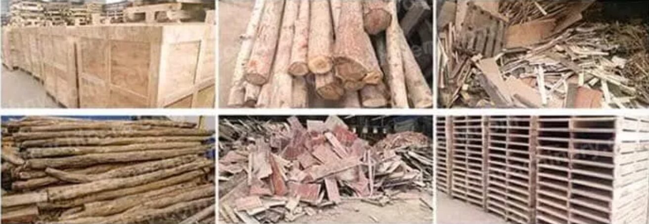
A green waste stream may include logs, branches, leaves, soil, and occasional stones. A wood recycling stream can contain pallets, nails, painted boards, and bulky offcuts. Municipal or commercial waste intended for RDF may include film, textiles, paper, plastics, inert material, and high-moisture organics. Tire recycling presents another set of requirements, including bead wire, reinforced rubber, and a need for controlled granule sizing.
Before selecting equipment, define the maximum feed size, average and peak hourly volume, moisture range, contaminant profile, and expected variations between loads. Also establish the final product specification. A plant producing boiler fuel may accept a wider chip range than a pellet plant. An RDF customer may require a narrow particle size and low chlorine or inert content. A tire processing customer may need wire-free rubber chips, crumb rubber, or powder.
These details determine whether the line needs primary shredding, magnetic separation, secondary size reduction, screening, drying, air separation, and storage. They also determine where wear protection and access for maintenance are most necessary.
Build the Line Around the Required Output
The best process route works backward from the product specification. If the final output must be below a defined size, consistent in shape, and dry enough for combustion or pelletizing, every upstream stage must support that result.
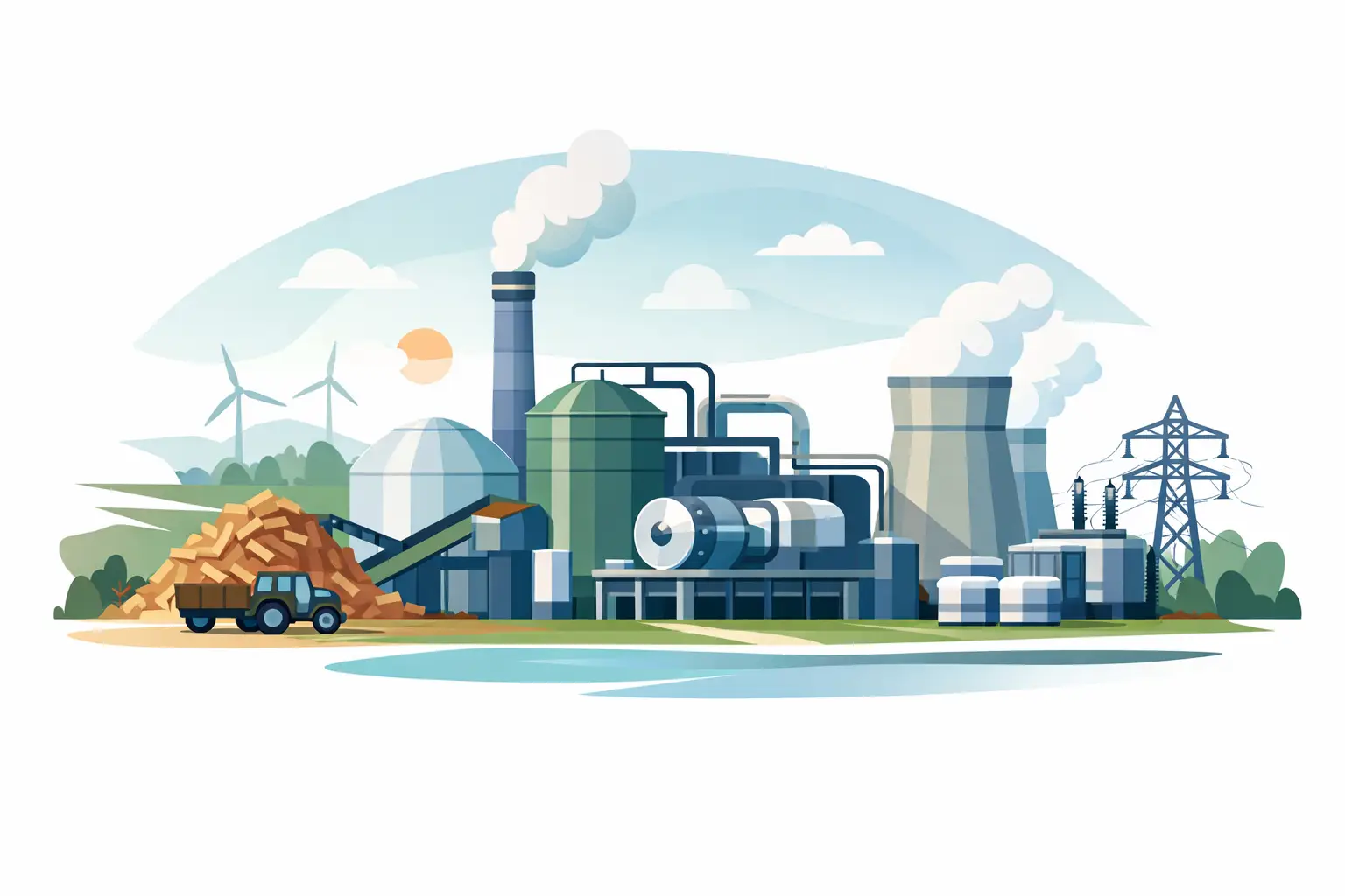
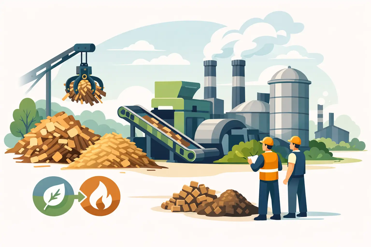
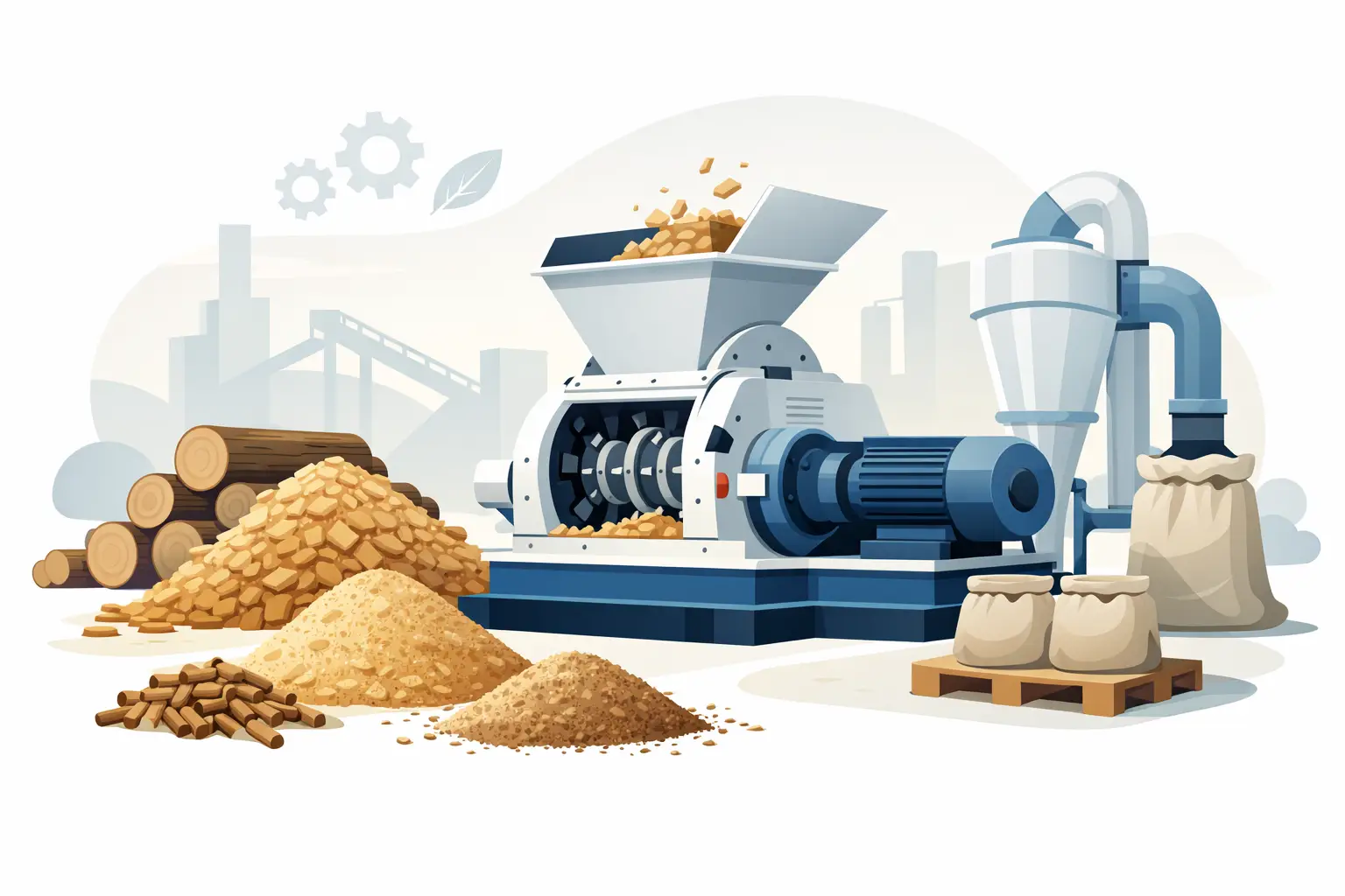
For wood biomass preparation, a typical route may begin with a receiving conveyor and feeding system, followed by a disc wood chipper or drum chipper for logs and clean wood. Green waste, pallets, and irregular wood residues may first require a horizontal grinder or a single-shaft shredder. A trommel screen can remove soil and undersize material, while a magnetic separator removes ferrous metal. If moisture exceeds the acceptable range, a rotary dryer can reduce moisture before final screening, storage, or densification.
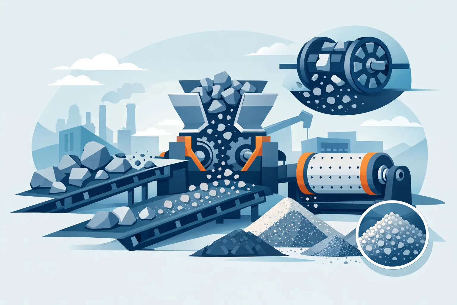
For RDF/SRF production, primary shredding opens bulky waste and reduces handling volume. Screening separates fines that may carry high ash or moisture. Ferrous and nonferrous separation can improve fuel quality, while air separation helps remove light film from heavy inert fractions or produces the desired light combustible fraction, depending on the process objective. Secondary shredding then creates a more uniform alternative fuel size.
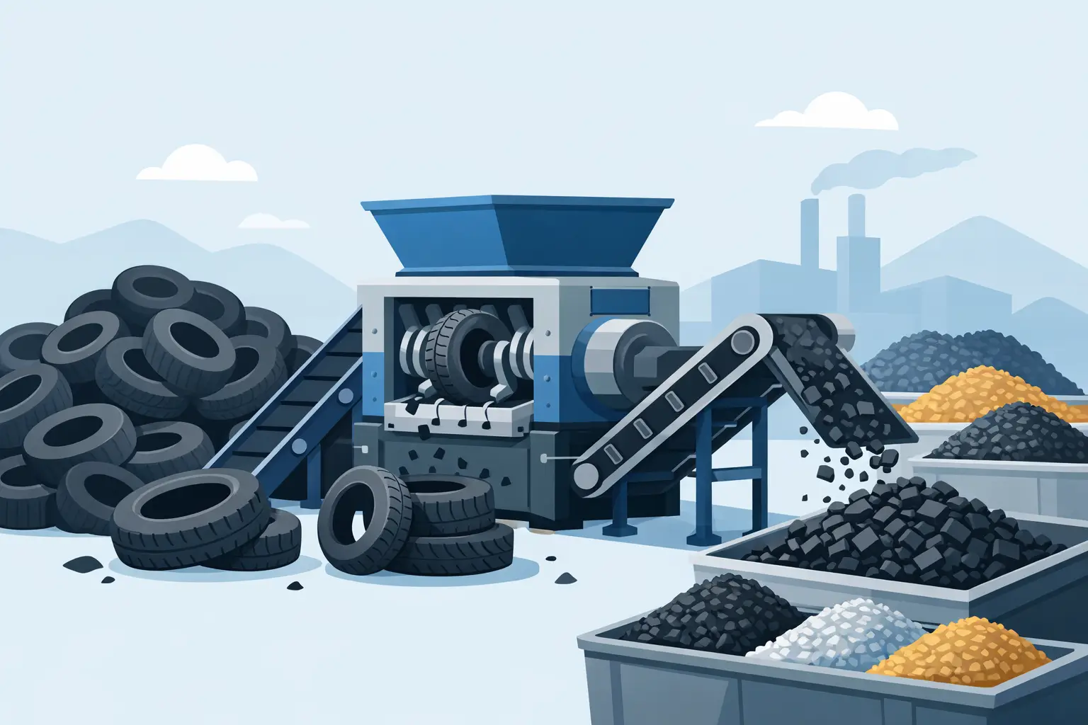
Tire recycling lines usually require staged reduction rather than one aggressive cut. A dual-shaft tire shredder handles whole tires and heavy tire sections. Downstream conveying, magnetic separation, secondary shredding, and rubber pulverizing can produce chips, granules, or fine rubber powder. The correct sequence depends on whether the project targets tire-derived fuel, civil engineering material, reclaimed rubber feedstock, or higher-value rubber products.
The trade-off is clear: more processing stages can improve product quality and marketability, but they also increase capital cost, energy use, footprint, and maintenance requirements. A complete line should include only the stages that create measurable operational or commercial value.
Select Machines by Duty, Not Brochure Capacity
Rated capacity is useful, but it is not enough for industrial purchasing. A machine rated for a certain tons-per-hour figure under ideal material conditions may perform very differently with wet, tangled, abrasive, or contaminated feedstock. The key design question is whether every machine can sustain the planned average throughput while absorbing normal peaks without becoming a bottleneck.
Primary equipment must be selected for the toughest material that will enter the plant. For example, a chipper intended for clean roundwood is not automatically the right machine for demolition wood with metal contamination. A shredder designed for light commercial waste may not be suitable for dense industrial scrap or whole tires. Rotor configuration, cutter material, screen size, drive power, hydraulic protection, and discharge design all affect real production performance.
Screening equipment also requires careful matching. Trommel screens are well suited to separating fines and different size fractions from many bulky or mixed materials. Flip-flow screening machines can be effective where wet, sticky, or difficult material would blind conventional screening media. The right choice depends on particle shape, moisture, required cut point, and the volume of fines.
Drying capacity should be designed according to water removal, not only wet material throughput. A rotary dryer handling 10 tons per hour of feed at a high moisture level may require much more thermal energy than the same tonnage of partially air-dried material. Fuel availability, emission controls, residence time, and downstream moisture requirements must be considered early in the project.
Engineer the Interfaces Between Machines
Most production interruptions occur at transfer points. Material can bridge in hoppers, wrap around shafts, spill from conveyors, or accumulate under screens. A successful line therefore treats conveyors, chutes, feeders, and storage as core processing equipment rather than secondary accessories.
Conveyors should be sized for peak flow and matched to the material’s bulk density and angle of repose. Inclined sections may need cleated belts. Wet or stringy waste may require wider belt widths, slower speeds, and self-cleaning arrangements. Chutes need sufficient slope and geometry to prevent bridging, especially after shredders and screens where material shapes are irregular.
Feed control is equally important. A metering conveyor or hydraulic pusher can maintain stable loading into a shredder, chipper, grinder, or dryer. Overfeeding increases amperage spikes, reduces particle consistency, and accelerates wear. Underfeeding wastes installed capacity. Variable-frequency drives and load-based control logic help keep the line within its most productive operating range.
A practical design also includes buffer capacity. Receiving hoppers, intermediate bunkers, and finished-product storage allow one part of the line to continue operating during short interruptions elsewhere. The correct buffer size depends on shift pattern, truck unloading schedule, machine maintenance intervals, and whether the plant can safely recirculate off-spec material.
Plan for Contamination, Wear, and Service Access
Recycling feedstock is demanding by nature. Metal, stones, sand, and unknown objects can damage cutting components and reduce output quality. Magnetic separation should be positioned where it protects downstream equipment and where removed metal can be discharged safely. In some applications, pre-screening before size reduction removes soil and abrasive fines before they reach high-wear machinery.
Wear parts should be accessible without excessive disassembly. Cutter knives, shredder blades, grinder screens, hammer elements, bearings, and conveyor belts need planned inspection and replacement intervals. A lower purchase price can become expensive if the design requires long shutdowns for routine service.
Safety engineering must be built into the layout. Include emergency pull cords, interlocked guards, lockout points, access platforms, dust collection where required, and fire prevention measures for dry biomass or combustible fractions. Control systems should provide fault indication, overload protection, and a logical start-stop sequence that prevents material from backing up through the line.
Specify the Project as a Complete Operating System
A strong technical inquiry gives the manufacturer enough information to engineer a line rather than quote isolated equipment. It should identify the material source, hourly and annual capacity target, incoming size range, moisture, contaminants, final product requirements, available power, installation footprint, and local environmental requirements.
It is also useful to define responsibility boundaries early. Confirm whether the supplier will provide process layout, equipment foundation loads, electrical control cabinets, field installation guidance, commissioning support, spare parts recommendations, and operator training. International projects should also clarify packing method, shipping terms such as FOB, CIF, or CNF, and the documentation needed for import and site acceptance.
Zhengzhou Jinpeng Machinery Equipment Co., Ltd. engineers integrated recycling and biomass processing systems around these operating conditions, combining shredding, crushing, screening, drying, and conveying equipment into application-specific lines.
The most productive next step is to turn your current material problem into a process data sheet. When feedstock variability, output specification, capacity target, and site limitations are defined clearly, custom recycling line design becomes an investment in stable production rather than a collection of individual machines.