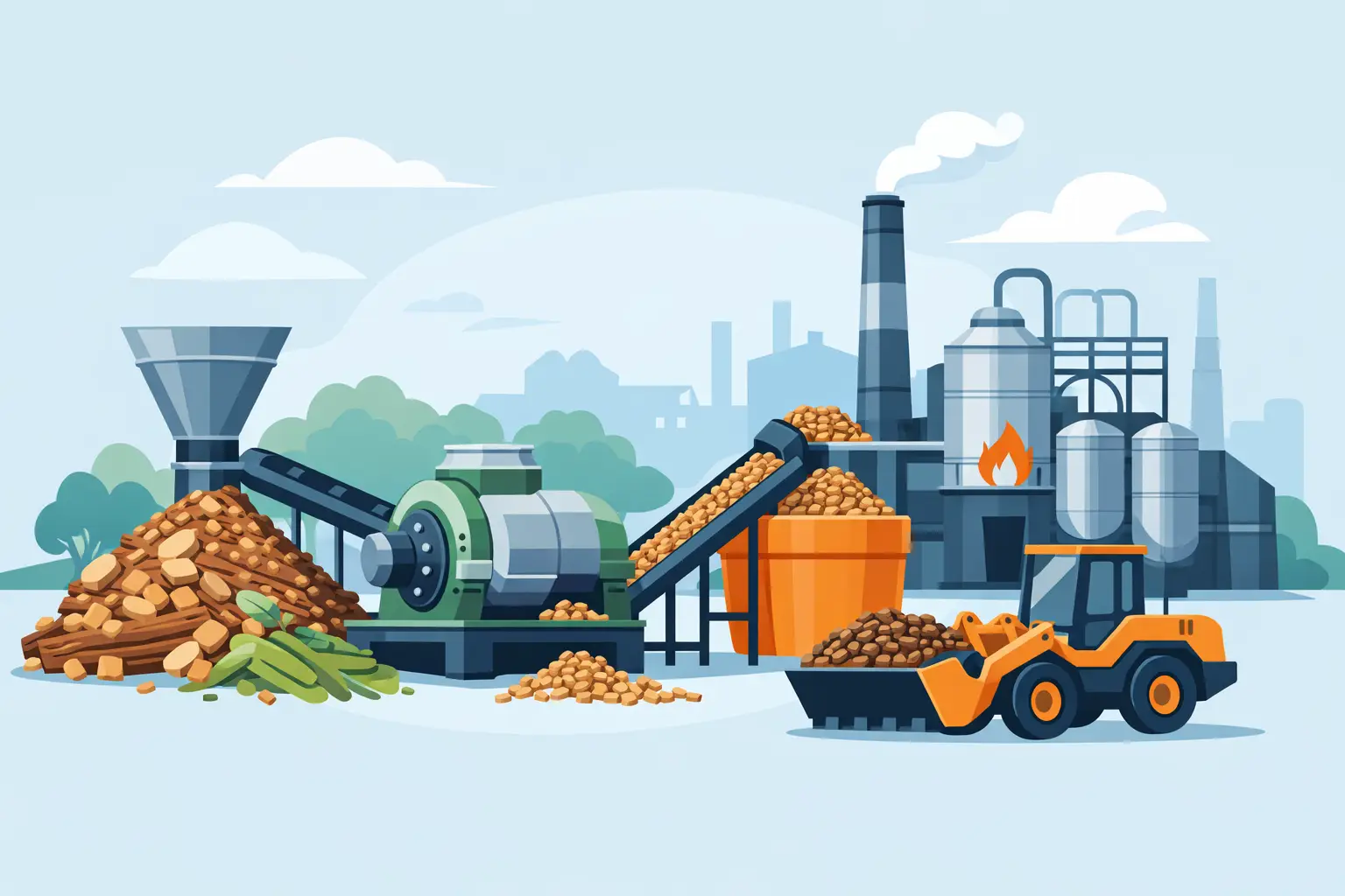
A biomass plant rarely loses output because of one obvious machine failure. More often, capacity is restricted by a mismatch between biomass plant components: an undersized infeed system, a chipper that receives inconsistent material, a grinder producing too many fines, or a dryer that cannot keep pace with wet feedstock. For plant owners and project engineers, the objective is not simply to buy equipment. It is to build a preparation line in which every stage supports stable, high-volume fuel production.
The right configuration depends on feedstock type, incoming size, contamination level, moisture, target particle specification, and required tons per hour. Wood residues, forestry slash, pallet waste, agricultural stalks, and green waste may all become biomass fuel, but they do not behave the same way in a processing line. A component layout designed for clean sawmill offcuts will not necessarily perform well on muddy logs, mixed demolition wood, or high-moisture yard waste.
Biomass Plant Components by Processing Stage
An industrial biomass preparation plant is best evaluated as a material-flow system. Material enters bulky, irregular, and often contaminated. It must leave as a consistent fuel suitable for storage, pelletizing, briquetting, gasification, or boiler combustion. Each component has a defined role in closing that gap.
Receiving, Conveying, and Metered Feeding
The receiving area establishes the operating rhythm of the entire plant. Feedstock may arrive by walking-floor trailer, loader, grapple, or conveyor from an adjacent wood yard. A receiving hopper or feed bin should provide enough buffer capacity to prevent brief supply interruptions from stopping downstream equipment.
Heavy-duty belt conveyors, chain conveyors, screw conveyors, and hydraulic push floors move material between stages. The selection depends on material geometry. Long branches, stumps, and bulky green waste may bridge in a conventional hopper, while fine sawdust requires controlled discharge to avoid flooding downstream equipment.
Metered feeding is particularly critical before chippers, shredders, grinders, and dryers. Variable-frequency drives and hydraulic feed systems allow operators to match feed rate to motor load. This prevents overload events, protects cutting tools, and helps maintain a consistent particle distribution.
Debarking and Primary Wood Reduction
When processing roundwood, forest residues, or logs for clean wood chip production, debarking is often an early requirement. Bark can be acceptable in some boiler fuels, but excessive bark changes ash content, moisture behavior, and fuel value. A wood debarker separates bark before chipping, producing a cleaner feedstock where the end-use specification demands it.
Disc wood chippers and drum chippers are primary reduction machines for logs, slabs, branches, and wood offcuts. Their role is to convert oversized material into chips of a controlled nominal size. Disc chippers are commonly selected for cleaner log streams and uniform chips. Drum chippers can provide high throughput for a broader range of wood materials, depending on the feed system and rotor design.
The key specification is not only motor power. Buyers should assess inlet dimensions, knife quantity, rotor diameter, allowable feedstock size, discharge chip size, and actual capacity for their material. A machine rated for high output on dry, straight softwood may deliver substantially less when fed wet hardwood branches with dirt and irregular geometry.
Shredding for Mixed or Difficult Feedstocks
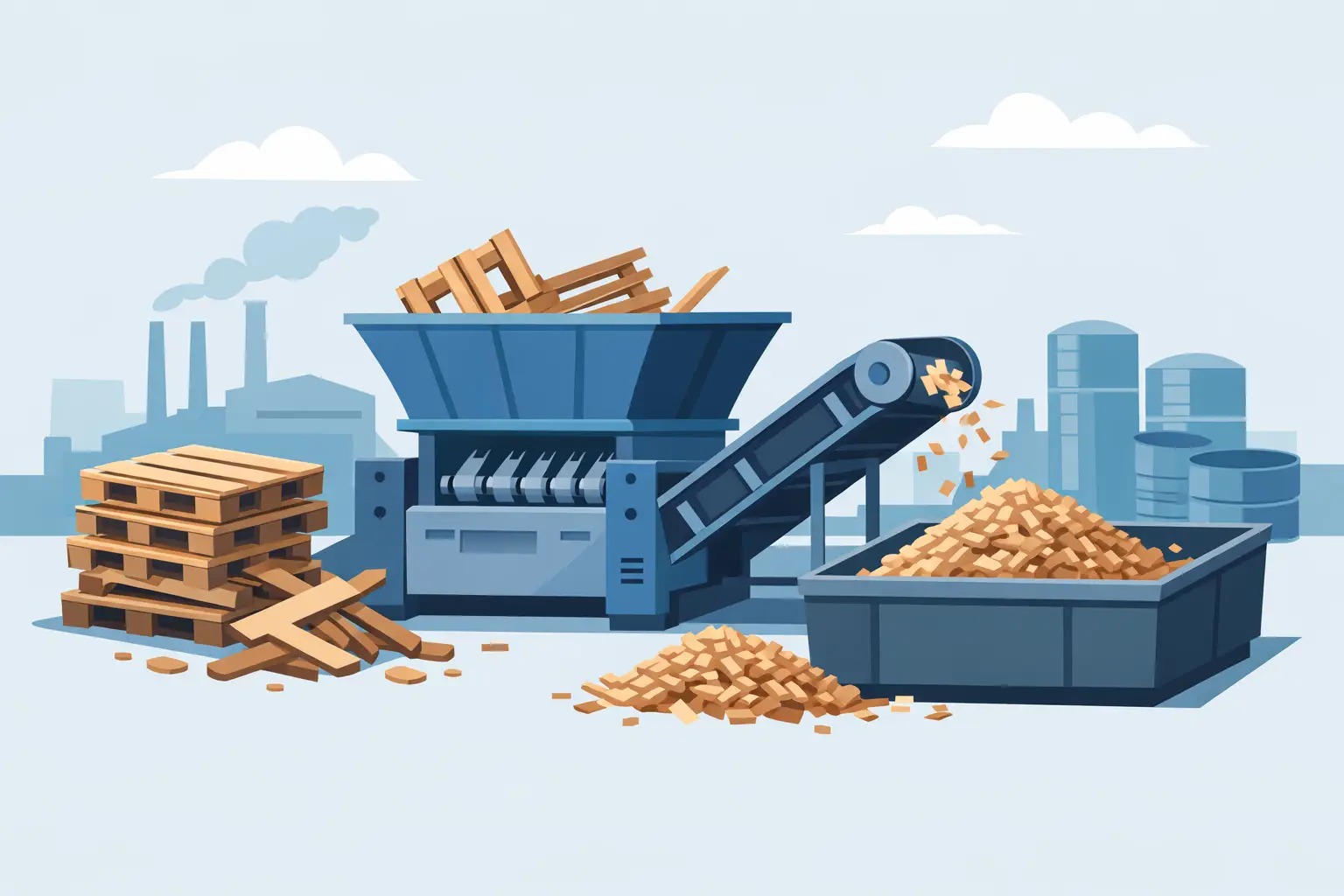
Shredders are often the correct first-stage solution when feedstock is heterogeneous. Single-shaft shredders use a rotor and hydraulic pusher to produce a controlled cut on materials such as pallets, furniture waste, demolition wood, green waste, and certain agricultural residues. Dual-shaft shredders use counter-rotating cutters to tear and reduce bulky material with less dependence on a precise feed orientation.
For biomass fuel preparation, shredding is valuable when material contains nails, hinges, plastics, roots, or irregular shapes that would create problems in a conventional chipper. However, a shredder is not automatically a substitute for a chipper. Shredded material can be more irregular in shape, and some fuel applications require a secondary grinding stage to achieve tighter size control.
A well-designed line may use a shredder for coarse reduction, magnetic separation for ferrous removal, then a grinder or chipper for final sizing. This sequence protects higher-precision equipment from damaging contaminants while improving usable yield.
Screening and Contaminant Separation
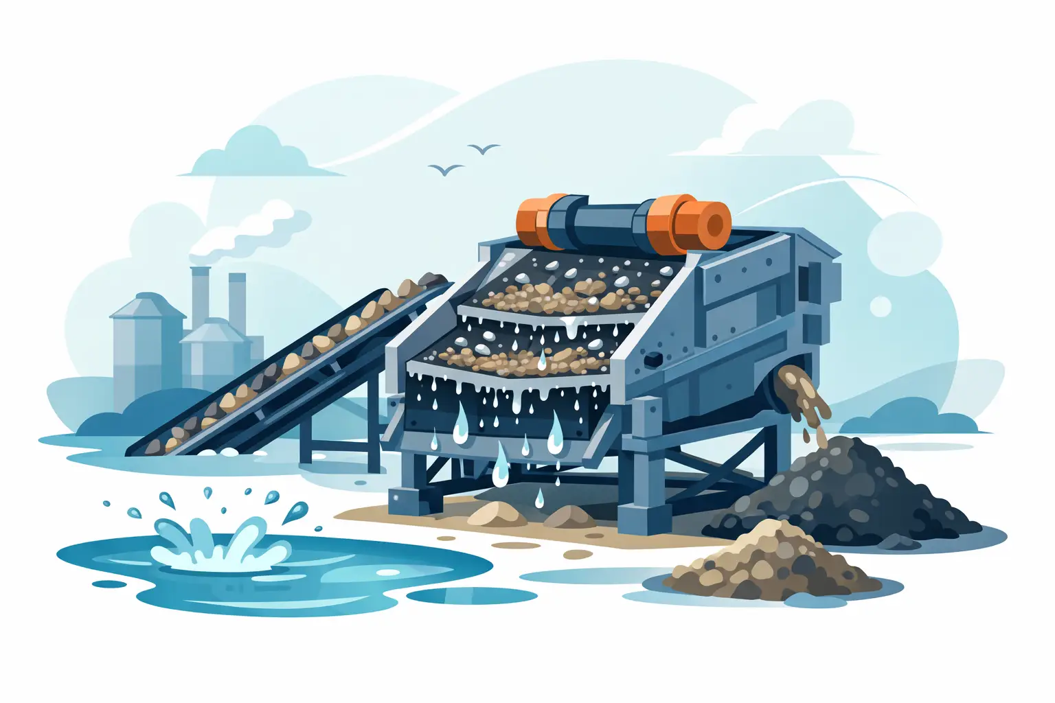
Screening determines whether the plant delivers a product that customers can use consistently. Trommel screens separate materials by size using rotating perforated drums. They are effective for classifying wood chips, compostable green waste, biomass fractions, and oversize recirculation streams. Flip-flow screening machines are suited to difficult, damp, sticky, or elastic materials that can blind conventional screen media.
Oversize material is normally returned to the reduction stage. Fines may be sent to a separate fuel stream, pellet feed process, or controlled storage area. Sending all fractions directly to the boiler or pellet mill can create uneven combustion, handling problems, and reduced product value.
Magnetic separators should be considered when processing post-consumer wood, pallets, construction wood, or material handled in metal-intensive environments. Removing ferrous contaminants before fine grinding reduces wear and protects downstream equipment. Depending on the feedstock, non-ferrous separation and manual picking stations may also be justified.
Fine Grinding and Particle Size Control
Fine wood grinder mills reduce chips, shreds, and coarse biomass into smaller particles for pellet production, briquetting, combustion systems, or densification. Screen opening, rotor speed, hammer configuration, and feed consistency all influence the final output.
Fine grinding improves particle uniformity, but it consumes energy and increases wear. Specifying a smaller screen than the end use requires adds cost without improving the finished fuel. For direct boiler fuel, a coarser product may be acceptable. Pelletizing usually requires finer, more uniform material, particularly when feedstock contains variable wood species or fibrous residues.
This is where plant design must follow the final product specification. A biomass line should be engineered backward from the required fuel size, moisture, bulk density, and contamination tolerance, rather than built around whichever reduction machine is available first.
Drying and Moisture Management
Moisture is one of the most significant variables in biomass processing. Wet material lowers effective heating value, raises transport cost per usable ton, complicates storage, and may limit pellet quality. Rotary dryers are widely used for continuous drying of wood chips, sawdust, agricultural biomass, and other bulk materials.
A rotary drying system typically includes the dryer drum, heat source, furnace or hot gas generator, induced-draft fan, cyclone or dust collection equipment, discharge conveyors, and process controls. The dryer must be sized based on both wet feed rate and the amount of water that must be removed per hour. Those are not the same calculation.
Overdrying wastes energy and can increase fire risk. Underdrying leaves a fuel that may not meet customer or process requirements. Moisture testing at receiving, after size reduction, and at dryer discharge gives operators the information needed to adjust feed rate and thermal input.
How to Specify Biomass Plant Components Correctly
Equipment selection should begin with operating data, not a generic capacity request. A request for “20 tons per hour” is incomplete unless it identifies whether that means wet or dry tons, average or peak rate, and what the material contains.
A practical technical brief should define at least these operating conditions:
- Feedstock sources, dimensions, species, bulk density, and moisture range
- Contamination risks, including soil, stone, metal, plastic, and treated wood
- Required output size distribution and permitted oversize or fines content
- Target hourly capacity, annual operating hours, and planned shift schedule
- Final application, such as boiler fuel, pellet feedstock, briquettes, gasification, or RDF/SRF blending
These details influence every major equipment choice. For example, high-moisture green waste may require screening before shredding to remove soil-heavy fines, while clean sawmill slabs may move directly through chipping and grinding. A plant receiving demolition wood needs more protection and separation than a line processing virgin forestry residues.
Integration Determines Plant Uptime
Individual machines can meet their stated capacities and still create a poor-performing plant if transfer points, controls, and storage are ignored. Conveyor widths must match material volume. Discharge heights must provide proper flow. Buffers must absorb variation between batch and continuous stages. Dust control must be considered around grinding, screening, and dry material transfer.
Automation also matters. Motor load monitoring, conveyor interlocks, emergency stops, level sensors, and centralized controls help operators identify restrictions before they become shutdowns. The goal is controlled throughput rather than forcing every machine to run at its maximum nameplate speed.
Zhengzhou Jinpeng Machinery Equipment can configure integrated systems that combine chipping, shredding, grinding, screening, drying, and conveying around the actual feedstock and required finished product. For export projects, equipment layout, electrical standards, spare-parts planning, and container loading requirements should be addressed during the engineering stage rather than after purchase.
The most productive biomass line is the one that treats material variability as an engineering condition, not an exception. Bring representative feedstock data, target fuel specifications, and realistic operating constraints into the first equipment consultation. That preparation gives every component a clear job and gives the plant a far better chance of delivering its designed capacity day after day.